Raspberry PI: USB powered HDMI-audio break-out

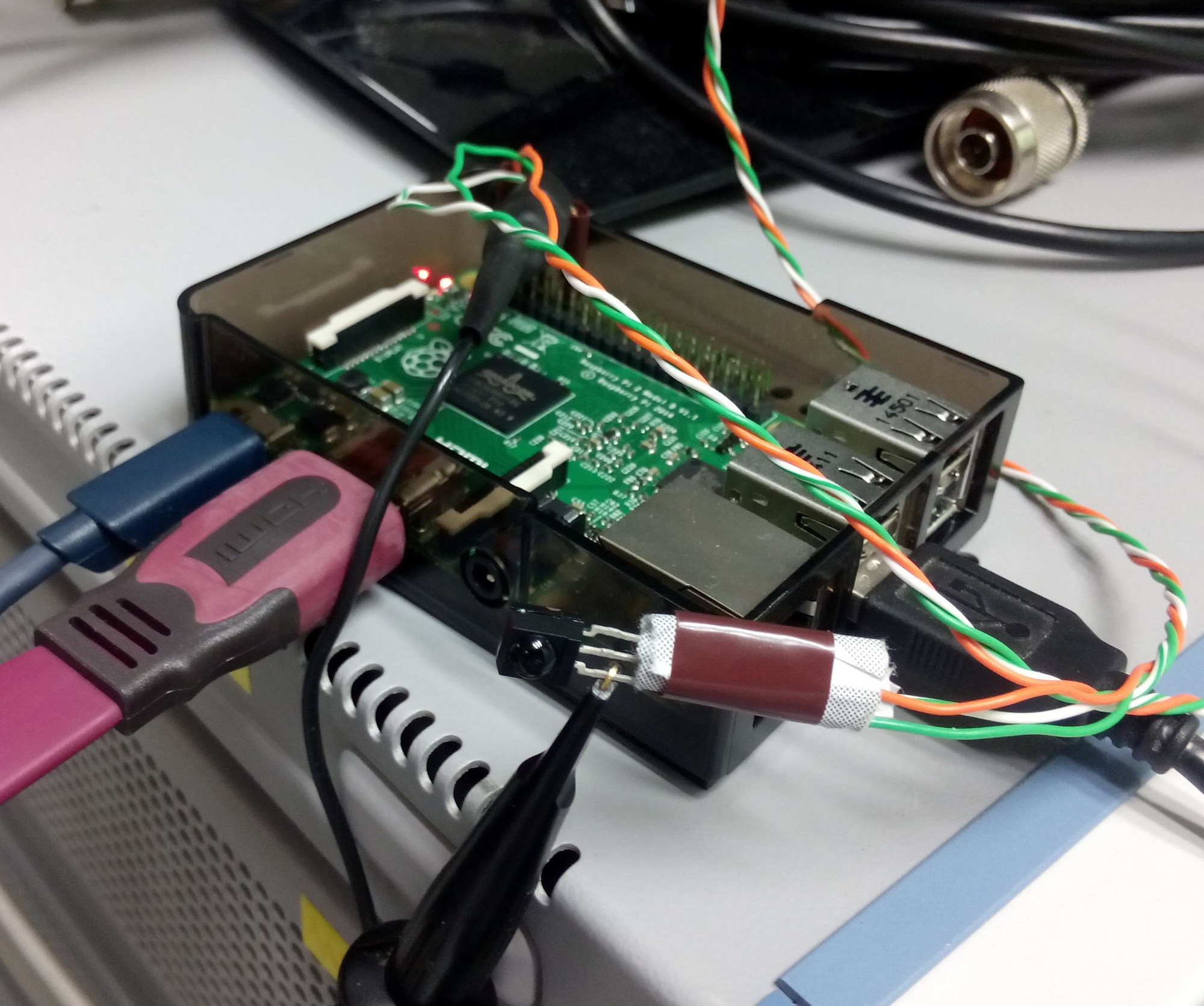
My original situation summarizes as follows:

  • a Raspberry Pi 2 is connected to my TV-screen via HDMI
  • FullHD-video-decoding and displaying in general works like charm.
  • digital audio (PCM and AC3) should be embedded in the HDMI-data-stream
  • my TV does not have a digital audio output but can consume the audio embedded in the stream
  • my audio-decoder and -amplifier does not have a HDMI-input
  • my software setup on the PI won’t allow the use of a HifiBerry-extension

What I would ideally need is something which

  • takes a HDMI-input,
  • splits out the digital-audio to a S/PDIF-output (optical or coaxial)
  • and forwards the original HDMI-signal on a HDMI-output.
  • Ideally this device is small and powered over USB (so that it doesn’t need an extra power-supply).

Believe it or not, this actually exists:

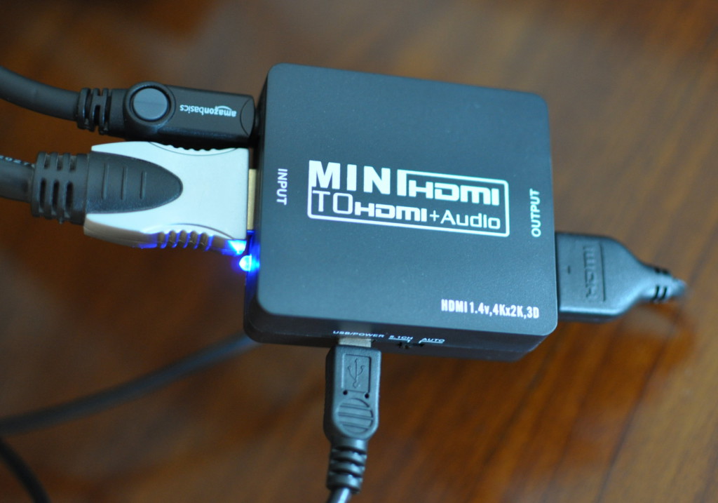
Self-powered HDMI-audio-splitter

It took me some time but I eventually found one on Amazon for around 25 euros. Other people have seen this kind of devices on eBay in 2014 and earlier.

Software problems

Inserting this device between the Raspi and the TV was straight forward. I just plugged everything on my running Pi and everything worked immediately – I thought. In fact there were two problems:

Problem 1: even when playing AC3-audio (2.0, 2.1 or 5.1), the Pi would only send PCM-frames.
Problem 2: after a cold-start, the Pi was not able to determine the correct resolution of my screen.

It turned out that both problems have the same root-cause:

When connecting a HDMI source to a HDMI sink (or when powering up one of them), the source gets some meta/configuration-information about the sink. It reads the so-called EDID-data. In it, among others, the source can find the supported screen-resolutions and the supported audio(-container)-formats.

Audio AC3-passthrough

Based on the list of accepted audio-formats the Raspi, or better the OpenMax-library (omx), will determine whether or not to pass-through AC3-audio (integrate it into the HDMI-data-stream). At some point in time that EDID data is read and if it does not list the capability, the software won’t even try to send AC3-data, but will decode it in software to Stereo-PCM.

But wait, now that there is the HDMI-splitter, where is the EDID-data coming from? Well, the splitter just passes through the information from my screen to the Raspi. My screen does not have a digital audio output. Most likely it tells sources that is doesn’t support anything other the PCM-audio.

Raspbian, which I’m using, has some pre-installed tools with which can be used to read and decode the EDID data. There is tvservice for reading EDID and dumping it to a file

pi@vdr-pi ~ $ /opt/vc/bin/tvservice -d edid-5.1.dat
Written 256 bytes to edid-5.1.dat

And there is edidparser for decoding the dumped .dat-file.

pi@vdr-pi ~ $ /opt/vc/bin/edidparser edid-auto.dat  | grep audio
HDMI:EDID monitor support - underscan IT formats:no, basic audio:yes, yuv444:yes, yuv422:yes, #native DTD:1
HDMI:EDID found audio format 2 channels PCM, sample rate: 44|48 kHz, sample size: 16|20|24 bits
HDMI:EDID has HDMI support and audio support

This last snippet shows the parsed the EDID-data. It was as I was suspecting. Nothing else then PCM is accepted by my HDMI-sink.

There seems to be several ways to convince the system that AC3-passthrough is possible though. The easiest for me was to use the switch provided for this reason on the HDMI-splitter. By default it is set to auto which gives the EDID seen above.

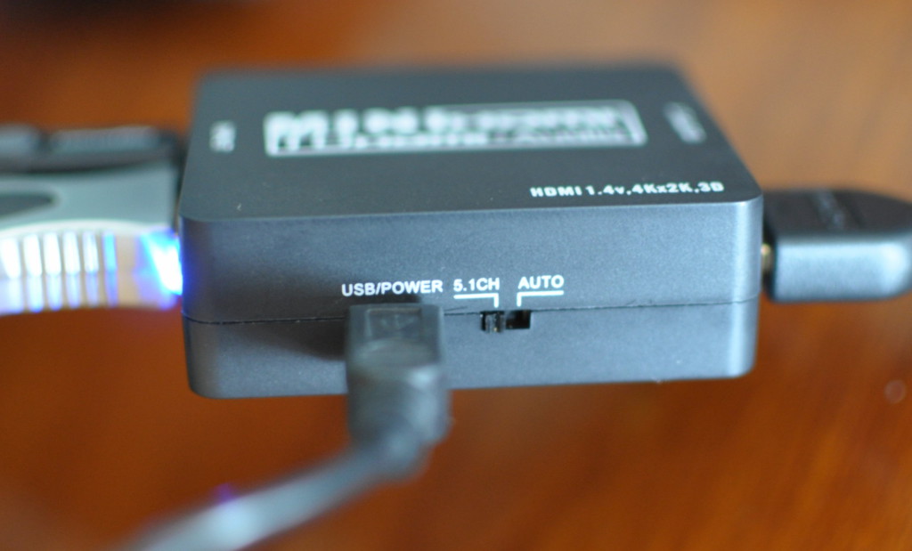
HDMI-audio-split: auto vs 5.1-mode

Putting the switch to 5.1 gives the following EDID-output and AC3-passthrough started to work, after I restarted the player-software:

pi@vdr-pi ~ $ /opt/vc/bin/edidparser edid.dat  | grep audio
HDMI:EDID monitor support - underscan IT formats:no, basic audio:yes, yuv444:yes, yuv422:yes, #native DTD:1
HDMI:EDID found audio format 2 channels PCM, sample rate: 32|44|48|88|96|176|192 kHz, sample size: 16|20|24 bits
HDMI:EDID found audio format 6 channels AC3, sample rate: 32|44|48|88|96|176|192 kHz, bitrate: 1536 kbps
HDMI:EDID found audio format 6 channels DTS, sample rate: 32|44|48|88|96|176|192 kHz, bitrate: 1536 kbps
HDMI:EDID has HDMI support and audio support

The other solutions I found suggested to change some boot-parameters in /boot/config.txt . Several EDID-related values can be set to override the EDID-values delivered by the sink. For this problem the HDMI_FORCE_EDID_AUDIO setting might work. I couldn’t use it; it conflicts with the solution of my other problem. (See here for more/all config.txt-parameters)

Screen resolution

By default the Raspi will select the native resolution of a screen as per EDID-data. My splitter is powered by the Raspi, so it is not running before the Raspi boots. It seems that at the moment the Raspi reads the EDID-information the splitter has not yet read the EDID from the screen. I don’t know what kind of data is received this way, but it is not correct.

I tried setting several HDMI-parameters in the config.txt nothing made it work. Except one: I forced the Raspi to read the the EDID-data from a file instead of the sink. For that, I put the edid.dat from above (this one I got with edidparser after having set the HDMI-splitter to the 5.1 mode) into the /boot-folder and added the following line to /boot/config.txt

hdmi_edid_file=1

Now everything worked as I wanted it to be.

Raspberry Pi 2: LIRC with an active-low IR-receiver with raspbian Jessie

On my journey of using the Rasberry Pi 2 for something useful, the moment has come where I want to plug an Infra-Red-receiver to it.

I’m not new to this, for years I used one plugged to my PC’s serial port (RS232). On the software side I used LIRC via the lirc_serial kernel module.

Just typing “lirc rasperry pi 2” on any available search engine gives me hints and How-Tos and motivation telling me that it won’t be difficult. Basically plugging the data-out-line (Vs) to a GPIO (the default being GPIO18), the 3.3V-line to a 3.3-volt-supply and the GND-line to ground should do the trick on the hardware side. An IR-receiver has three “legs”: Vs, 3.3V and GND. Mine has the GND in the middle, Vs left and 3.3V right (from the front view, where the half-bulb is).

I’m using Raspian Jessie and thus a recent kernel which uses DeviceTree for configuring the board’s hardware capabilities (previously this low-level board-layout-configuration was compiled into the kernel). To make the lirc_rpi-module work, the system needs to reserve GPIOs for it at boot-time. On a fresh jessie-installation that means I only need to un-comment one line (a DeviceTreeOverlay-line) of the config.txt-file in /boot:

# Uncomment this to enable the lirc-rpi module
dtoverlay=lirc-rpi

I plug the device using GPIO18 for data-in, I check the voltage, I chang the config.txt, I reboot, I run the mode2-tool and tap on my remote-controls. And nothing appears.

Fortunately, to debug such issues, I have access to superior tools, in this case an oscilloscope and, even more important, a competent colleague with hardware-knowledge. We, or better he, find(s) the problem within 2 minutes. Alone I would have wondered and doubted everything.

IR receiver on RPI, with probe plugged

After plugging the Raspi and its IR-receiver to the oscilloscope (probing the data-line of course) and putting the trigger level low enough we can observe the following sequence appearing when playing around with a remote control:

IR receiver on RPI, pull-down-active

As my colleague takes the first glimpse at this curve he immediately shouts: “it is missing a pull-up-resistor”. What makes him say that is the amplitude-delta of only 1 volt compared to the expected 3.3 volt.

This IR-receiver is an active-low receiver: it forces or drives the line to 0 when it wants to transmit a zero and it does nothing on the line to signal a one. To have the signal bounce back to the 3.3 volt when the device releases a pull-up-resistor is needed. Which is a high-Ohm-resistor (10K for example) coupling the data-line with the 3.3 volt supply line. The opposite is a pull-down-resistor: coupling the data-line with the ground for devices which are active-high and thus driving a 1 to signal a one and nothing to signal a zero.

Neither-nor is present in my setup which is the reason for the 1-values to be stuck at ~1 volt. Depending on the load here and there on the GPIO-PADs of the Raspi we could have also seen 2 volt or even nothing.

While my colleague looks for a high-Ohm resistor I’m sure that the chip-maker has thought of this problem and that there is an internal pull-up or pull-down on each GPIO-pad which can be activated. After quick search I find indeed what I was looking for: setting a GPIO-pull-up (or down) is a parameter to the dtoverlay of lirc-rpi.

# Uncomment this to enable the lirc-rpi module
dtoverlay=lirc-rpi
dtparam=gpio_in_pull=up

After applying this change and rebooting, running mode2 gives me the numbers printed out I expect and on the oscilloscope a clean amplitude of 3.3 volts is seen:

IR receiver on RPI, pull-up-active

Raspberry Pi 2, Raspbian Jessie and WiFi vs. Ethernet at boot-time

I just installed Raspbian Jessie on my new Raspberry Pi 2. I’m using an Edimax EW-7811Un USB WiFi-adapter as a primary network device which I want to configure cleanly within my dis
tribution. Cleanly, in the sense of changing as little as possible the system’s configuration-files and scripts.

Raspberry Pi 2Of course I found several nice tutorials (1 2 3) which indeed helped me to figure how to do it properly
and gave me a good start (especially for wpa_supplicant.conf, which I won’t detail here) . However, the original content of the config-files mentioned there, wasn’t matching with what I found on my installation. Maybe it is because Jessie is still quite new as of writing this.

Starting with the /etc/network/interfaces-file. It mentions eth0 (the wired ethernet port) and two wlan-devices and it says they are all configured manual.

auto lo
iface lo inet loopback

iface eth0 inet manual

iface wlan0 inet manual
    wpa-conf /etc/wpa_supplicant/wpa_supplicant.conf

iface wlan1 inet manual
    wpa-conf /etc/wpa_supplicant/wpa_supplicant.conf

Manual in this context means that the ifplugd takes over the network configuration. Ifplugd detects a physical connection and launches a dhcp-client to complete the interface-configuration. As of writing this, it does not properly take care of wlan-devices, however this it is how ifplugd is configured (from /etc/default/ifplugd).

INTERFACES="auto"
HOTPLUG_INTERFACES="all"
ARGS="-q -f -u0 -d10 -w -I"
SUSPEND_ACTION="stop"

My RPI2 will be used mainly via WiFi, but for debugging reasons I might plug the wire. Hence I’d like the system to always (try to) configure the WiFi-device and optionally the wired if a cable is plugged. To achieve this, here is what I did.

First I changed the way wlan0 is configured in interfaces, telling it to automatically be configured when the networking-service is started (at boot-time):

auto wlan0
allow-hotplug wlan0
iface wlan0 inet dhcp
    wpa-conf /etc/wpa_supplicant/wpa_supplicant.conf

Then I told ifplugd to no more using all devices but only eth0. I ran:

sudo dpkg-reconfigure ifplugd

And during the follow dialog asking me for “static interfaces to be watched by ifplugd’ I replaced auto by eth0. This makes /etc/default/ifplugd look as follows:

INTERFACES="eth0"
HOTPLUG_INTERFACES="all"
ARGS="-q -f -u0 -d10 -w -I"
SUSPEND_ACTION="stop"

This does exactly what I want with very few changes to the system’s files, thus clean.

UPDATE 30/10/2015:

I just did an apt-get update of my jessie installation and noticed that upstream has changed the interface-file. It now contains the allow-hotplug-lines I added to my interfaces. However, this does not change anything regarded the problematic I had on my system.